

The micro a plug has the id pin grounded while the id in the micro b plug is floating. Usb 3 reduces the time required for data transmission reduces power consumption and is backward compatible with usb 20.
 Connector Basics Learnsparkfun Micro Usb Female Wiring Diagram
The ground pin is connected to the ground of microcontroller.

micro usb female pinout. Two for power 5v gnd two for differential data signals labelled as d and d in pinout. With space being even more confined on may items like todays modern cell phones an even smaller connector solution was needed and accordingly developed. The device that has a micro a plugged in becomes an otg a device and the one that has micro b plugged becomes a b device.
Well they dont and i had to dig around all over the internet to find enough information to clear things up. Known as the usb micro connector again both usb micro a and usb micro b versions are available. Of the remaining four pins two pins pin 1 and pin 5 are used to provide the vcc and ground.
Usb a b 20 and 30 cable pinout the usb cable provides four pathways two power conductors and two twisted signal conductors. Micro usb pinout signals usb is a serial bus. Micro usb plugs have a similar width to mini usb but approximately half the thickness enabling their integration into thinner portable devices.
Otg adds a fifth pin to the standard usb connector called the id pin. Pinout of micro usb 30 connectorusb 30 is the successor of usb 20. The type of the plug inserted is detected by the state of the pin id.
The micro a connector is 685 by 18 mm with a maximum overmold boot size of 117 by 85 mm while the micro b connector is 685 by 18 mm with a maximum overmold size of 106 by 85 mm. Here is the pinout shown from the end of the plug. The usb device that uses full speed bandwidth devices must have a twisted pair d and d conductors.
The micro b connector is becomming more and more popular on small devices. You would think that when a great company sells a micro usb plug they would publish a very clear concise guide on how to wire it up. So now you dont have to.
The supply voltage of vcc is 5v and is usually provided from the microcontroller itself. Micro usb cable uses 4 shielded wires. The micro usb jack has five pins through which the power and data is transferred the 4th pin id is used for mode detection this indicates if the usb is used only for power or for data transfer.
 4 Pin Rj11 Male Connector Diagram Online Wiring Diagram
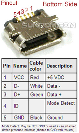 Micro Usb Connector B Female 5 Pin Smd 4358 Sunrom Electronics
 Micro Usb Wiring Diagram Mouse Best Wiring Library Micro Usb
 Usb Female Wiring Wiring Diagram
 Amazoncom Uxcell A11121400ux0134 Shielded Usb Type B Female Port 4
 1 4 Jack To Usb Wiring Diagram Wiring Diagram

Comments
Post a Comment